ExpressLRS 2.4GHz PWM Receiver, R24-P
ELRS-R24-P
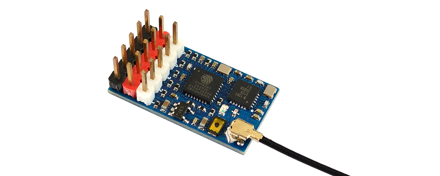
ELRS-R24-P Specifications
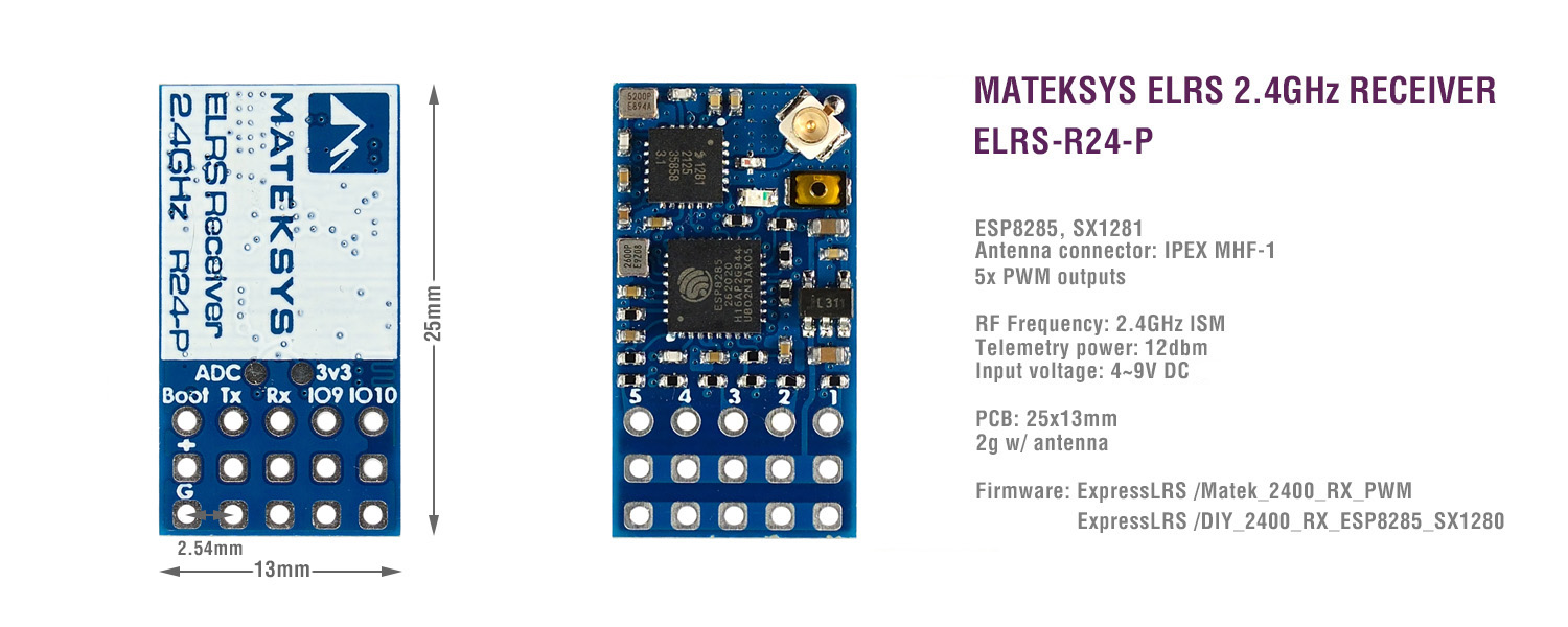
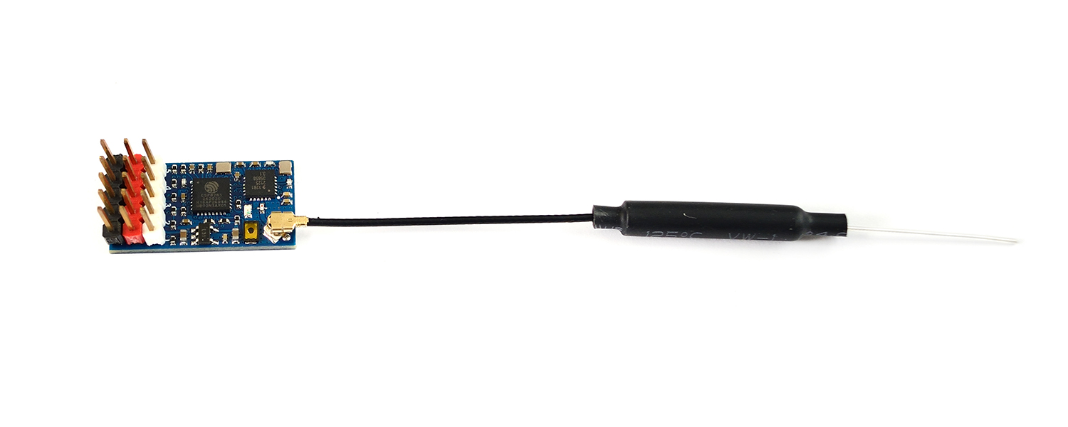
- ESP8285, SX1280/1281
- Antenna connector: IPEX MHF 1
- 5x PWM outputs
- RF Frequency: 2.4GHz (2400~2480MHz)
- Telemetry power: 12dbm
- Receiver protocol: PWM or CRSF
- Input voltage: 4~9V DC @ “+” pad
- Power dissipation: 45mA(binding), 85mA(wifi mode)
- PCB size: 25mm x 13mm
- Weight: 2g w/ antenna
- Packing: 1x ELRS-R24-P, 1x IPEX MHF1 Antennas
Firmwares
- ExpressLRS MATEK_2400_RX_PWM, or DIY_2400_RX_PWMP, PWM receiver via 1~5 PWM outputs
- ExpressLRS DIY_2400_RX_ESP8285_SX1280, CRSF Serial receiver via TX and RX
- Firmware update via UART or WIFI
Tips
- ExpressLRS wiki for PWM receiver, Click HERE
- Make sure Receiver and TX module both are running ExpressLRS 2.0
Traditional Binding
- Receivers have ExpressLRS fw V2.0 preloaded without BINDING_PHRASE
- Power on and off your receiver three times
- Make sure the LED is doing a quick double blink, which indicates the receiver is in bind mode
- Use the [BIND] button on the Transmitter Lua script, which sends out a binding pulse
- Receiver will switch to slow blink once it has received binding pulse.
- Power off and power on receiver again. If the receiver LED switch to solid on from slow blink, it’s bound with your transmitter.
Flashing with ELRS configurator
- MATEK_2400_RX_PWM or DIY_2400_RX_PWMP
- If use it as normal Serial receiver, flash it with Target DIY_2400_RX_ESP8285_SX1280
Flashing with ESP_NodeMCU-PyFlasher
- Connect receiver to USB-TTL module(RX-TX, TX-RX, 5V-5V, G-GND)
- Connect USB to PC while pressing and holding the boot button in.
- open ESP_NodeMCU-PyFlasher
- select Serial port of USB-TTL module, load firmware ELRS_V2.0.0_NoPhrase_ELRS-R24-P.bin , select “Dual Output(DOUT)” and “Yes.wipes all data“
- click “Flash NodeMCU“
- after flashing, Power off and power on your receiver, receiver will enter binding mode(quick double blink).
Troubleshooting
- If receiver can’t be flashed via WIFI or BFpassthrough when it come with preloaded firmware. You may recover it by flashing it via UART.
- Wire the receiver into the USB-TTL adapter, with TX on receiver connected to the Rx on the USB-TTL, and RX on receiver connected to the Tx of the USB-TTL. Wire 5V and GND of the USB-TTL to 5V and GND of the Receiver. Press the boot button while powering the RX on, and release – the LED should now be solid.
- Select the target MATEK_2400_RX PWM or DIY_2400_RX_PWMP, and “UART” for Flashing Method, set your bind phrase and Firmware Options and once done, click on Build and Flash.
comparison
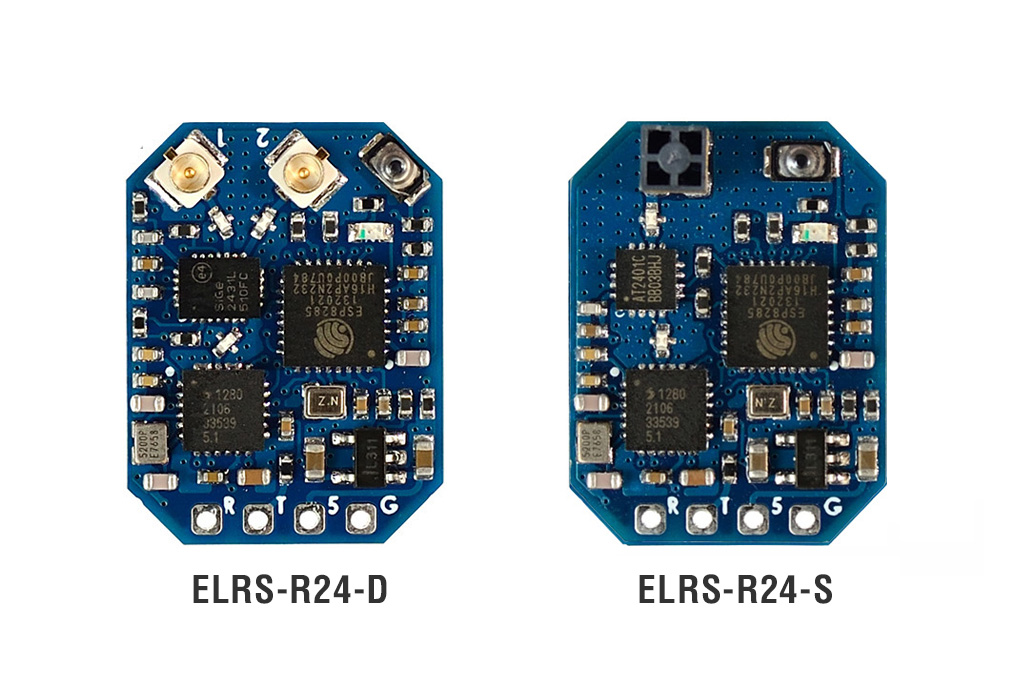
Comparison in ELRS-R24 series
| SKU | R24-P | R24-D | R24-S |
| RF Frequency | 2.4GHz | 2.4GHz | 2.4GHz |
| Antenna | IPEX MHF1 | 2x IPEX MHF1, Diversity | SMT Antanna |
| PA/LNA | / | SE2431L | AT2401C |
| Telemetry | 12dbm | 23dbm | 20dbm |
| LNA Rx_gain | / | 12.5dB | 12dB |
| CRSF Serial receiver | DIY_2400_RX_ESP8285_SX1280 | MATEK_2400_RX | MATEK_2400_RX |
| PWM receiver | MATEK_2400_RX_PWM | / | / |
Comparison between ELRS-R24-P and CRSF-PWM converter
| SKU | R24-P | CRSF-PWM-6 | CRSF-PWM-C |
| Receiver with ELRS direct PWM output | CRSF to PWM Converter/Decoder | ||
| PWM outputs | 5 | 6 | 10 |
| RF Frequency | 2.4GHz | compatible with any CRSF protocol receivers (including 433MHz, 868MHz, 915MHz, 2.4GHz) |
|
| PWM frequency | 50Hz | 50, 100, 160, 330, 400Hz | |
| Telemetry ID | RSS, Qly SNR | RSSI, Qly SNR RxBt, Curr, Capa, Bat%, GPS, GSpd, Hdg, Alt, Sats |
|
| CH remapping | support | No | |
Resellers

