FAQ
Do not use excessive flux !!! Flux mixed with soldering dross is conductive !!!
Red/Blue/Green LEDs light up/blink normal when FC booting, but FC can‘t connect to configurator, or can’t go into DFU mode.
- Intall DFU and STM VCP drivers, Click Installing Betaflight/INAV for details
- Make sure INAV firmware version is compatible with configurator version, e.g. use configurator 3.0 for fw 3.0.x, use configurator 2.6 for fw 2.6.x
- Unplug USB and close configurator, plug USB back in and run configurator again.
- Try other USB cables
- Check if there is dry joint on USB connector pins
- There is known bug that INAV configurator Chrome version can’t flash firmware in DFU mode.
- If GPS or other peripherals are connected to UART1 or UART3 of F4/F7/H7 chip and these peripherals are powered ON while connecting USB. FC can’t enter DFU mode. It is related to DFU protocol used in the STM32 bootloader, not hardware and PC driver issue.
- Unsolder/disconnect all peripherals from FC board. Try connecting bare FC to configurator.
- Test resistance between 3v3 and G. normal resistance should be K ohm class.
- DFU mode can’t be bricked. Try reflashing it in DFU mode.
Flight controller freeze when booting
- Make sure you have it flashed with right target/firmware.
- Try reflashing it in DFU mode.
- It is a good practice to type CLI “defaults” after every flashing to erase fragment of data/settings.
- DO NOT try to use a diff or dump from other version. Start settings from scratch.
*****
- Make sure the soldering iron you are using is ESD-safe. some iron tips may float at arbitrary voltages unless an additional grounding wire is used. you can easily kill chips when soldering if soldering iron is not grounded properly.
*****
-
Pls take a few high resolution and in-focus photos of Flight Controller still installed and wired, then you can take it apart. These photos will be a huge help for troubleshooting if you decide to email us for service.
-
Before you start troubleshooting steps, make sure you have removed all wires connected to the FC board.
-
LED doesn’t light up or weak light and MCU/3.3V LDO chip heat up fast after connecting USB or battery. FC can’t connect to configurator.
-
- Finger can’t touch MCU surface or LDO3.3V chip for more than 1 second, Most likely MCU is dead, there is short circuit in core of MCU.
-
The obvious symptom is short circuit or low resistance between 3V3 and G.
- MCU health can be tested easily by connecting USB only. Wrong wiring on MCU I/O or ESD from peripherals could damage MCU. so once the board was soldered or wired. MCU death is not covered by warranty.
- If you have hot air work station, you might replace MCU. Flashing it in DFU mode after replacing MCU.
-
Red LED(3v3 indicator) doesn’t light up or weak light when connecting FC USB to PC
- Disconnect USB, then test the resistance/continuity between 3v3 and G, 4v5 and G
- Resistance between 3v3 and G should be Kohm grade.
- If there is continuity between 3v3 and G
- Double check if there is solder ball/splash on the capacitors/MCU pins
- Unsolder/Disconnect all peripherals from FC board, test it again.
- If there is continuity between 4v5 and G
- Unsolder/Disconnect all peripherals from FC 4v5 rail, test it again.
- If no continuity
- Try another USB cable
- Check if there is dry joint on USB pins
-
Flight controller can power on via USB, but can not power on via battery.
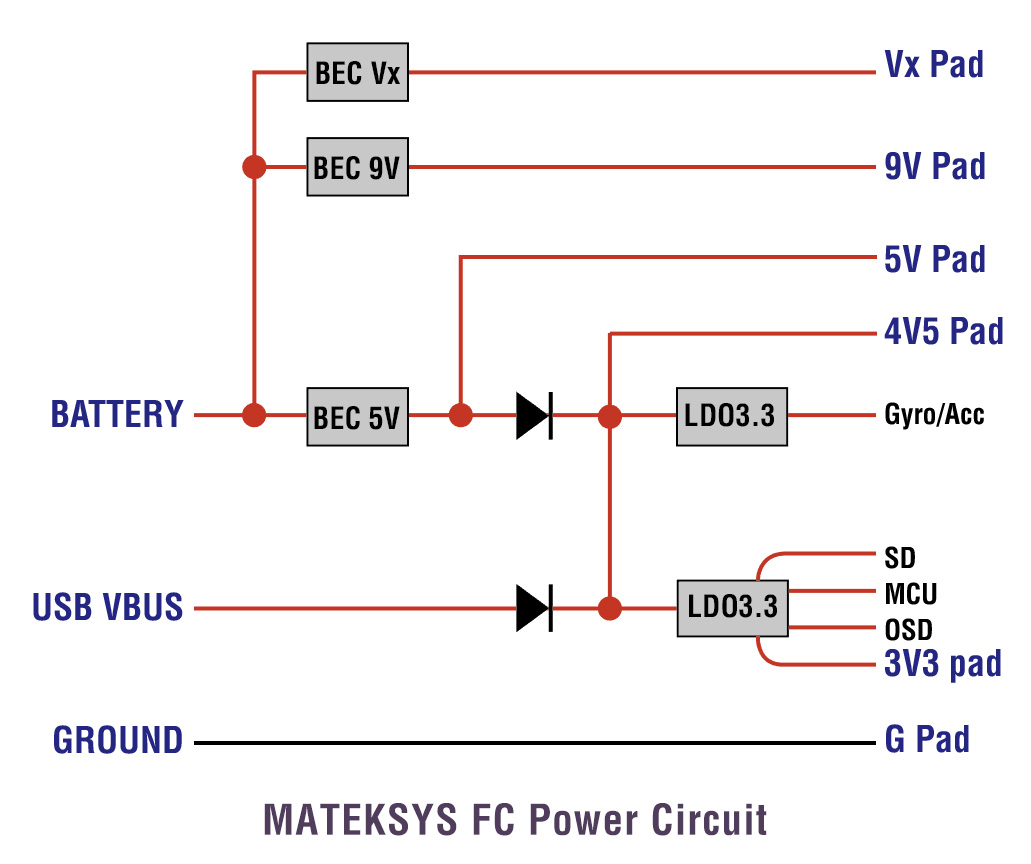
- Usually it is caused by short circuit on 5V rail or faulty 5V regulator.
- Test the continuity/resistance between 5V and G without any battery and USB connected.
- If you have wired some peripherals to the board, Unsolder/Disconnect all peripherals from 5V rail, Test the continuity again.
- If no continuity between 5V and G, test the voltage on 5V and 4v5 pad while connecting battery only. If no 5V output, regulator chip could be dead.
- Double check if FC is flashed with right Target.
- Reflash it with full chip erase selected.
- DO NOT try to use a diff or dump from other versions.
- In particular check devices on the I2C bus. Errors with that bus (magnetometer, barometer, AirSpeed) tend to really screw with the operation of the FC in a way.
- check I2C devices wiring(SCL-SCL, SDA-SDA), and check if I2C devices are powered on when FC initialization.
- Try desoldering/disconnecting I2C devices from FC board to see if FC can boot normal.
- Reflash FC with full chip erase selected, CLI “defaults” after reflashing, then reconfigure I2C devices in configurator.
- or set I2C speed in INAV configurator
- Some I2C sensors are reported to work unreliably on default 400kHz speed. INav allows to reduce I2C clock rate to 200kHz and 100kHz to allow these picky sensors to function properly.
- If compass sensor is not recognized or hangs when setting, please try CLI command “set i2c_speed = 200KHZ” before reporting a bug.
- Gyro/Acc can’t be detected when FC initialization.
- Check if FC is flashed with right Target
- Check if there is solder ball/splash on Gyro chip, or solder ball/splash on capacitors nearby Gyro
- Make sure INav firmware version is compatible with configuration version, e.g. use configurator 2.5.x for firmware_2.5.x
- Check if motor and servo output is enabled in “configuration” tab.
- Check if motor and servo mixers are configured in “Mixer” tab.
- Don’t enable “External PWM servo driver”
Servo
- WING series FC
- Test the voltage between “Vx” and G when FC is powered via battery.
- If no voltage on Vx rail, disconnect/desolder all servos from Vx rail, test it again.
- Other series
- Test the voltage on servos power source, e.g. 5V
- There is a known issue that some 433/900M transmitters/receivers could interfere servos. put them far from servos, or try 2.4G radio system.
Motor
- check if ESC is powered on.
- check if ESC protocol selected is compatible with your ESC.
- check if ESC PWM range is calibrated if using PWM/oneshot/multishot protocol.
- check the Arming prevention flags and OSD warning when you try to arm FC.
- GPS can work with any spare UART
-
Red(inav)/Gray(BF)/ GPS icon at top of configurator,No GPS(ArduPilot)
- Check GPS wiring and cables continuity, GPS TX – FC RX, GPS RX – FC TX
- Check if GPS module is powered on.
- Check if GPS is configured on proper Uart in Ports Tab.
- Check GPS protocol in configuration tab, usually use UBLOX protocol for most of GPS modules.
- Try swapping protocol from ublox to NMEA, or from NMEA to ublox.
-
Blue(inav)/Bright(BF) GPS icon at top of configurator, no satellites signal, No Fix(ArduPilot)
- Put GPS nearby windows or outdoor.
- Try testing GPS and FC with USB power only, make sure other peripherals(VTX, Receiver, Camera,etc) are not powered on.
-
DO NOT set any unnecessary GPS paramaters if you don’t know how they work. with ArduPilot, just need to set SERIALx_protocol = 5 on corresponding UART. don’t need to set any other GPS paramaters, leave all others by default. with INAV/Betaflight, just need to configure GPS on on corresponding UART. enable “GPS” and “ublox protocol”. don’t need to set any baudrate. LESS IS MORE.
- It is known that HD cameras(Gopro, Split, Tarsier, DJI etc) could interfere GPS signal, If GPS can’t get 3D fix after powering on for dozens of minutes. try turning off HD camera.
- There are reports that Frsky X8R could interfere GPS. If you are using X8R and GPS can’t get 3D locked. power off X8R then test.
-
Tips
-
UBlox NEO-M9N, MAX-M10S, SAM-M10Q series all don’t have dataflash built in. once GNSS is powered off and the supercapacitor run out. the settings will back to default.
-
UBX protocol is bidirectional. Flight controller firmware can change parameters in GNSS module via UBX protocol. You don’t need to set GNSS module Baud and Frequency in u-center.
- Sometimes FC firmware command could also mess up the parameters in GPS module. If you are sure wiring and setup are all right. but flight controller can’t detect the GNSS module or GNSS can’t receive any satellites after dozens minutes. Try connecting GNSS to USB-TTL module to computer, use U-center to revert GPS to default configuration, then check the GPS status in u-center.
- The M10Q-5883, SAM-M10Q, M10-L4-3100 provide the ability to reset the receiver. when powering on, bridging “RST” pad to Ground for at least 100 ms will trigger a cold start. RESET will delete all information and trigger a cold start.
-
-
Revert GPS to default configuration
- Install U-Center software
- Attach your GPS to a USB-UART adapter(USB-TTL module, CP210x, FTDI, etc) and connect it to your computer.
- Launch U-Center software. Clicking the connect button and choosing the correct serial port and baudrate shall make the software connect with the GPS and displaying received data in the data view window contiuniously. If nothing appeared, check your connection and serial port parameters and try other baudrate.
- Open the configuration view by pressing F9.
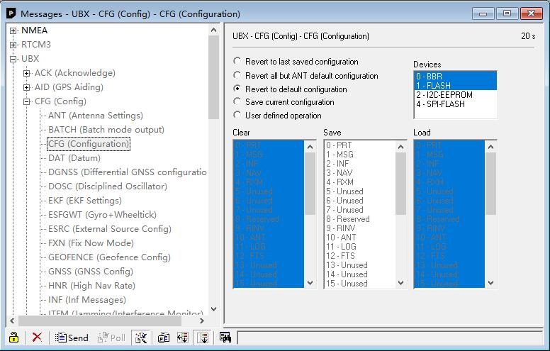
- Navigate to UBX -> CFG -> CFG and select “Revert to default configuration” and click “Send” button located on the bottom.

-
PPS LED not working when GPS 3D fix
- https://www.u-blox.com/sites/default/files/GNSS-FW3.01_ReleaseNotes_%28UBX-16000319%29_Public.pdf, section 3.2.2
- Start with u-blox GNSS FW 3.01, timepulse is aligned with UTC time and that time is set valid only after leap second is downloaded. That could take up to 12.5 min. You can change timepulse configuration to GPS time(in ucenter, UBX->CFG->TP5->[1] GPS TIME) and then timepulse should be produced as soon as valid fix is present.
- 1PPS output or not doesn’t affect GPS 3D fix performance. if GPS can receive enough satellites and has good 3D fix. Your Quad/Plane are good to go.
-
If the I2C errors doesn’t keep going up after boot. that is normal. The errors occur during FC initialisation before the I2C speeds are all set up right.
I2C bus speed selection
- Some I2C sensors are reported to work unreliably on default 400kHz speed. INav allows to reduce I2C clock rate to 200kHz and 100kHz to allow these picky sensors to function properly.
- If compass sensor is not recognized or hangs when setting, please try CLI command “set i2c_speed = 200KHZ” before reporting a bug.

*** F405-STD, F722-STD & F405-mini have no 5V regulator builtin. They need to be powered up via external 5V source. VCC pad on these FC are for battery voltage detection only.
Need low ESR capacitor on your ESC to absorb the BEMF switching noise.
4in1 ESC, one 1000uF
4x individual ESC, 220uF~470uF per ESC
- Rubycon: ZLH, ZLG, ZLQ
series - Panasonic: FM, FR series
- Nippon Chemi-con: KZE, KZH, KZM series
- Nichicon: UHV series
-
We have got a few reports that coating caused short circuit between power rails, and resistance changing between MCU/chips pins.
-
If you are not sure of its properties, conformal coating is NOT recommended before you confirm every function works well.
-
Once the board is coated, no way to troubleshoot
DJI Air unit/Vista can work with ANYYYYYYY spare UART/softserial of ANYYYYYY flight controllers supported by Betaflight/INAV/ArduPilot firmware
- Power —> Power source according to air unit voltage spec.
- GND —> FC GND
- UART RX —> FC spare UART_TX/Softserial_Tx
- UART TX —> FC spare UART_RX/Softserial_Rx
- GND —> FC GND
- DJI HDL —>FC any spare UART_RX(F7,H7), FC SBUS pad (F4)
- If not using DJI radio, no need to connect 5th GND and 6th DJI HDL to Flight Controller.
- Betaflight: enable MSP on corresponding UART
- INAV: select “DJI FPV VTX” on corresponding UART, DO NOT enable MSP
- INAV 5.x.x doesn’t support DJI air unit O3
- ArduPilot: check out the wiki for settings. https://ardupilot.org/plane/docs/common-msp-osd-overview.html
- SERIALn_BAUD = 115, SERIALn_OPTIONS = 0
- DJI Air Unit old versions: OSD_TYPE = 3, SERIALn_PROTOCOL = 33, MSP_OPTIONS = 0
- DJI Air Unit O3: OSD_TYPE = 5, SERIALn_PROTOCOL = 42, MSP_OPTIONS = 4
We are using a high precision current amplifier on H743-WLite / H743-WING /F405-WTE/F405-VTOL / F722-WING / F722-WPX/ F405-WSE/ F765-WING/F765-WSE/
This amplifier offers precision accuracy specifications of 2μV Input Offset Voltage and gain error of 0.05%. (The most common current amplifier is TI INA139/INA169 which has Input Offset Voltage 200μV & gain error of 0.5%. Usually INA139 can’t provide a valid reading when the current is less than 1A at 100A current sensor range)
This high precision amplifier is sensitive to ESC noise. make sure ESC is filtered well.
- If you are using Blheli32 ESC, setting ESC PWM to 48K in BLHeli32Suite can reduce the ESC noise. higher ESC PWM rate, lower noise.
- Sometimes need to add a 330~680uF low ESR capacitor on the ESC power pads of Flight controller to absorb the switching noise.
- Rubycon: ZLH, ZLG, ZLQ
series - Panasonic: FM, FR series
- Nippon Chemi-con: KZE, KZH, KZM series
- Nichicon: UHV series
- There are 2 types of Blackbox logging device, SD card and on-board flash chip(e.g. 16M, 32M).
- The majority of Flight controllers use just one storage media. If the FC integrates SD card socket, and doesn’t integrate NOR/NAND flash chip. “No dataflash chip found” will show at the top right corner of INAV/BF configurator.
- SD card must be formatted in FAT32. (not exFAT or NTFS).
- Once formatted in the FAT32 format only 4 GB will be usable for the Blackbox usage even if the SD card capacity is 16GB, 64GB, 128GB etc.
-
Plug SD into FC, then connect FC to USB only (no battery connected), Open Blackbox Tab, waiting Filesystem initialization.
- Some SD cards have compatibility issue. you might need to try more SD cards sometimes.
- SAMSUNG microSD EVO plus(Red) is recommended.
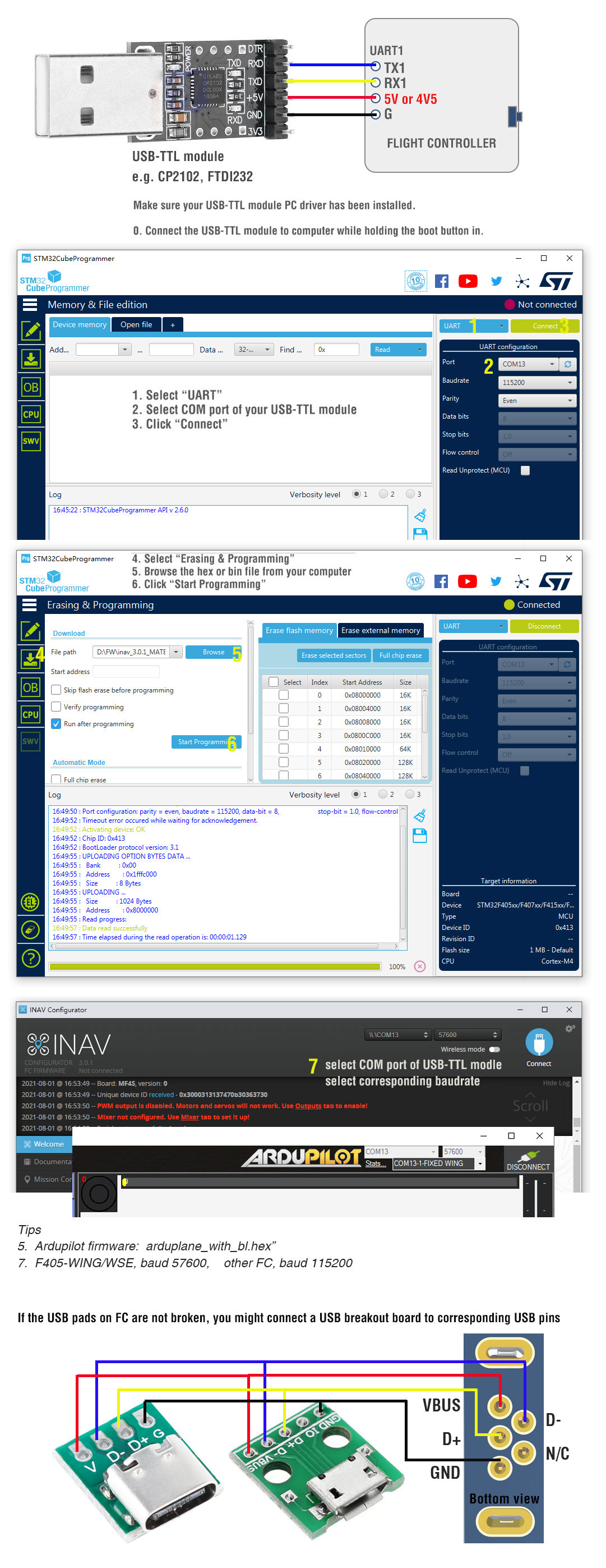
- https://www.st.com/en/development-tools/stm32cubeprog.html
- You may download Windows version from here en.stm32cubeprog_v2-3-0.zip
- Flashing via USB-TTL is compatible with INAV and ArduPilot, is not compatible with Betaflight because BF don’t have MSP enabled on UART1 by default.

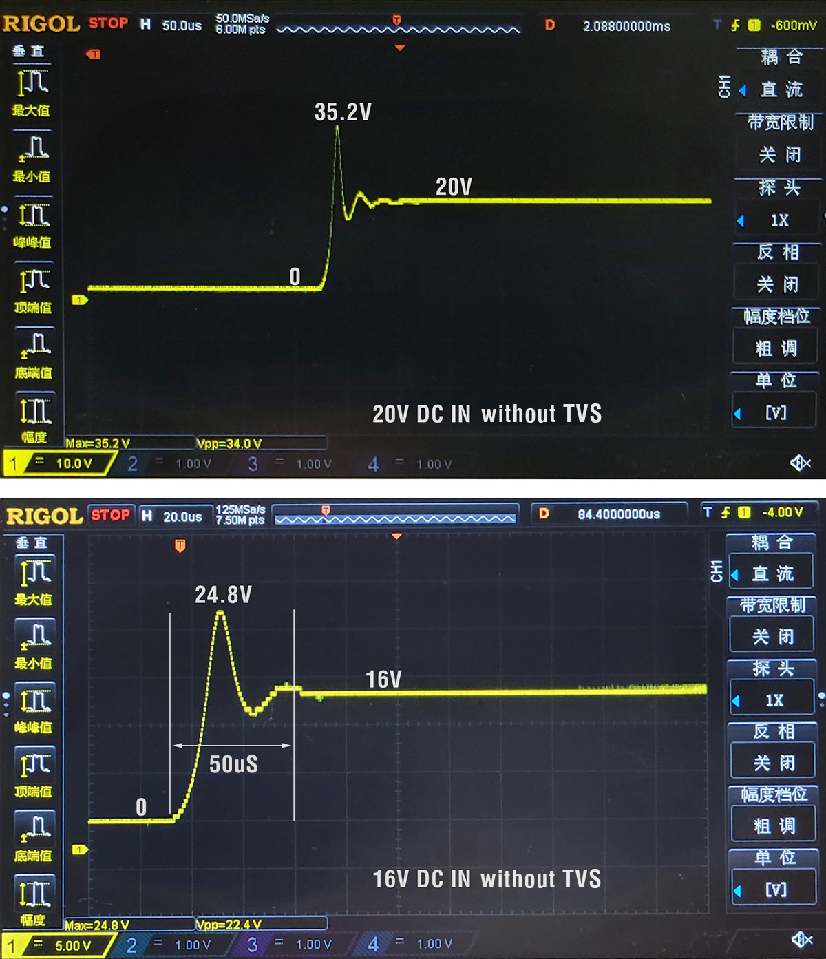
The regulator chips damage usually happens at the moment when the battery is plugged.
If we check the voltage surge on oscilloscope, the transient voltage occurs within 50us when the battery is connected. sometimes the transient voltage can be twice of the battery voltage.
If you are using 6S LiPo or higher, We strongly recommend adding TVS diodes.
What is a TVS Diode and How Does it Work?
- The Transient Voltage Suppression diode (TVS) is a component that is commonly used for transient protection. (Not to be confused with zener diode or schottky diode.) It consists of a p-n semiconductor junction that becomes conductive during a transient voltage spike. In normal circumstances, it appears as an open circuit despite a small leakage current.
- When the voltage on the transient voltage suppressor rises across its threshold voltage(Minimum Breakdown Voltage), the avalanche effect of the semiconductor causes the p-n junction to become a low-impedance path that channels away the excessive current. The response time of the TVS diode is extremely fast, often expressed in picoseconds.
- Minimum Breakdown Voltage to Maximum Clamping Voltage – The clamping voltage is the voltage limited by the TVS diode in the event of a transient within the limit of the specified peak current. for 6S LiPo, 28V Minimum Breakdown Voltage is is recommended (e.g. SMBJ26A, SBMJ28A). SMBJ33A for 8S LiPO.
- The placement of the TVS diode is also important. It is a good practice to place TVS diodes as close to the power source as possible.
- en.wikipedia.org/wiki/Transient-voltage-suppression_diode
- What are TVS diodes, Semtech Application Note SI96-01

- open INAV configurator — sensors tab.
- check if “Baro” readout is normal. “Baro” is the raw readout of Barometer sensor. If “Baro” responds correctly to height changes. Barometer sensor is working fine.
- OSD and navigation related features use “Alt” readout. “Alt” is the Altitude computed by the all AHRS sensors, ARHS is related to barometer/gyro/acc/compass/GPS and PID settings. If one of these is not set/calibrate right. “Alt” readout will be all over the place.
- e.g. if the acc is not calibrated. you will not get right “Alt” readout. It’s easy to verify, Flip the FC 180 degree, then check the Baro and Alt readout. “Baro” should be stable, “Alt” will climb and descend when flipping FC.
- You may check out this video. Why INAV climbs rapidly in Altitude Hold mode? by Paweł Spychalski
| SKU | I2C-INA-BM | CAN-L4-BM | HCS-150A |
| Type | Shunt resistor | Shunt resistor | Hall effect |
| Interface | I2C | CAN | Analog,ADC |
| Voltage Range | 0~85V | 0~85V | 0~69V |
| Current Range | 0~204.8A | 0~204.8A | 0~150A |
| Compatible | ArduPilot | ArduPilot | ArduPilot INAV Betaflight |
| Features | Digital, High precise | Digital, High precise | No power loss and heat on current sensor components |
